


Optimum development options and strategies for water injection development of carbonate reservoirs in the Middle East
[SONG Xinmin*  , LI Yong]
, LI Yong]
|
|


Through the research on several carbonate reservoirs developed in the Middle East, the basic characteristics of different types of carbonate reservoirs are determined, and a set of high-efficiency water injection development options and strategies are presented. Hidden baffles and barriers exist in carbonate reservoirs in the Middle East, so the reservoirs could be divided into different separated development units based on the baffles and barriers characteristics. Flexible and diverse profile control techniques such as high angle wells and simple and applicative zonal water injection have been introduced to improve the control and development degree of reservoirs. Three principal water injection development methods suitable for different carbonate reservoirs in the Middle East are proposed, including the combination of crestal gas injection and peripheral water injection, bottom interval injection and top interval production (buoyancy underpinning), and “weak point and strong plane” area well pattern. Based on the characteristics of very low shale content, fast and far pressure transmission in the Middle East carbonate reservoirs, a large well-spacing flood pattern is recommended, and reasonable development strategies have been made such as moderate water injection rate and maintaining reasonable production pressure drawdown and voidage replacement ratio, so as to maximize the recovery of reservoirs in the none or low water cut period.
In recent years, China’ s oil and gas business in the Middle East has expanded rapidly, where the most important oil and gas production base overseas has been built. The reservoirs in the Middle East are mostly marine carbonate reservoirs, which are quite different from those in China[1, 2, 3, 4]. Carbonate reservoirs in the Middle East are dominated by bioclastic limestone in structure traps, with few structural stages and some lithologic pinches in local areas. The reservoirs are dominated by Mesozoic Cretaceous gentle slope platform, marginal platform limestone and Jurassic tidal-flat dolomite reservoirs, which are controlled by sedimentation and diagenetic transformation. They are large in scale with good reservoir connectivity. However, many barriers and baffles and high-permeability layers exist vertically in the reservoirs, and these reservoirs are mainly developed by regular flooding well pattern[5, 6, 7, 8]. The developed reservoirs in the Middle East are mainly porous carbonate with fairly good reservoir qualities. The average porosity is 14-25%. They are mainly reservoirs with weak edge and bottom aquifer, weak natural energy, and low current oil recovery factor. Especially in Iraq and Iran, they are mainly developed by depletion, with recovery factor of 4.5-7.0%. At present, their development is shifting to water injection. However, due to strong heterogeneity of the reservoirs, developed barriers and baffles, strong vertical heterogeneity and high-permeability layers, the water injection pilots indicated that irregularly-distributed barriers and baffles and “ thief zones” had resulted in low sweep efficiency and low water injection swept volume. Therefore, the successful water injection development for this type of reservoirs is challenging[9, 10, 11, 12]. The development scheme for large-scale bioclastic limestone reservoirs is still under exploration stage and lack of mature experience, it is necessary to establish the optimum development options for this kind of reservoirs as soon as possible. Through the in-depth study of several developed carbonate reservoirs in the Middle East, the common problems existing in water injection development of different carbonate reservoirs have been clarified, and high- efficiency water injection development modes and development strategies for carbonate reservoirs have been proposed in this work.
Carbonate reservoirs in the Middle East are mainly porous carbonate reservoirs, and each oilfield has a main bioclastic limestone reservoir, which plays a significant role in oilfield development and performance. The following basic characteristics are found based on the research of carbonate reservoirs in the Middle East (Table 1): (1) The main oil reservoirs are developed continuously and stably across the whole oilfield, with large oil-bearing areas (165-1 770 km2) and thick reservoir thickness (60-120 m). (2) The reservoirs are mostly porous bioclastic limestone with fairly good reservoir qualities, the average porosity is 14-25% and permeability is (2- 38)× 10-3 μ m2. (3) They are unsaturated reservoirs with normal temperature and pressure system, and oil density is mainly between 820-870 kg/m3. (4) The oilfields have large reserves, with geological reserves of (3.0-55.9) × 108t, and the primary reservoir usually contributes to 40-99% of the total oil reserves of the field. (5) They are mainly reservoirs with edge/bottom aquifer and weak natural energy, some of which are bulk reservoir with bottom aquifer and gas cap, and the reservoir types are complex and diverse. (6) In Iraq and Iran, carbonate reservoirs are usually under natural depletion with low recovery factor, and some of them turn into water injection development.
| Table 1 Basic data of carbonate reservoirs in the Middle East. |
This paper describes the basic characteristics of carbonate reservoirs in the Middle East from five aspects, which are petrology, pore-throat structure, barriers and baffles, fluid properties, and reservoir heterogeneity.
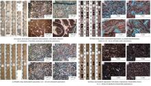
Compared with clastic rocks, the chemical composition of carbonates is relatively simple, but their structural components are complicated, and they are more likely to be dissolved and crystallized, which contribute to the complexity of carbonate reservoirs[13]. Carbonate reservoirs in the Middle East are mainly in the Jurassic and Cretaceous, of which the Jurassic reservoirs are mostly dolomite and the Cretaceous reservoirs are mostly limestone. In terms of depositional environment, reservoirs are mainly developed in tidal flat, gentle slope, reef shoal and slope environments. From the view of lithology, framestone, calcirudite, grainstone, packstone, wackestone and dolomite are common developed in the reservoirs (Fig. 1).
 | Fig. 1. Petrological characteristics of main limestone reservoirs in the Middle East. |
The primary carbonate reservoirs in the Middle East are deposited in a clean marine environment with basically no clay minerals. In addition, crystallite and micrite limestone are crystalline carbonate rocks despite their fine grain size (similar to that of siltstone-mudstone in clastic rocks). Meanwhile, unlike clastic rocks which require a long transportation distance to deposit and form a reservoir, deposition of carbonate reservoir is mainly autochthonous and usually with short transportation distance. Therefore, clastic reservoirs generally have a favorable connectivity direction due to mudstone barriers. Unlike clastic reservoirs, shale content is very low to none in carbonate reservoirs in the Middle East, and they are characterized by better lateral connectivity, which makes the reservoir pressure transmitting with faster speed and longer distance. This is the fundamental difference between marine carbonate reservoirs in the Middle East and terrestrial sandstone reservoirs in China.
Reservoirs in the Middle East are mainly porous carbonates, which developed various pores with different origins and sizes, including bio-framework pores, intergranular dissolved pores, moldic pores, intergranular pores, matrix micro-pores, intercrystalline pores, and intrafossil pores (Fig. 1). In addition, the pore structures are complex, and some of which have multimodal features. As can be seen from Fig. 2a, the pore throats of MB2-1 sublayer in the Halfaya Oilfield are mainly bimodal, and in some special cases are multimodal. Complex reservoir pore structure leads to poor correlation between porosity and permeability, and wider permeability distribution range with similar porosity are found in data of core samples (Fig. 2b). The complexity of reservoir microscopic pore structure also brings about great challenges to efficient water flooding development in the later stage.
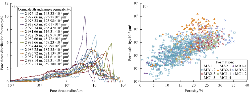 | Fig. 2. The distribution of pore throat radius in MB2-1 of Halfaya Oilfield (a) and the relationship between porosity and permeability of Mishrif reservoir (b). |
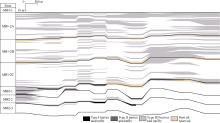
Barriers and baffles in carbonate reservoirs are different from those in sandstone reservoirs. Barriers and baffles in carbonate reservoir are commonly petrophysical interlayers, which are relatively subtle, and act as barriers in the development. For example, the average reservoir thickness of Mishrif Formation in the Halfaya Oilfield is 119 m with significantly different petrophysical properties of reservoir vertically. According to the core data and well logging analysis, its barriers and baffles can be divided into three types (Table 2). In this reservoir, a suite of superimposed carbonaceous mudstone, marlstone and packstone with a thickness of about 3 m are developed stably in lateral direction between MB1 and MB2 members. Petrophysical baffles and poor oil layers (act as barriers) between MB1-2C and MB1-2B sublayers are relatively stable. In MB1 member, the number and thickness of type II and type III baffles both increase gradually from bottom to top (Fig. 3). The barriers and baffles in the Mishrif Formation of the Halfaya Oilfield are characterized by wide lateral distribution and good continuity, which are the important basis for the division of development units.
| Table 2 Statistics on parameters of barriers and baffles in the Mishrif reservoir of Halfaya Oilfield. |
 | Fig. 3. The distribution profile of SW-NE trending (minor axis) barriers and baffles in the Mishrif reservoir of Halfaya Oilfield. |
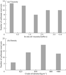
The crude oil of carbonate reservoirs in the Middle East are mainly light oil with low viscosity of less than 3 mPa· s (Fig. 4a) and density of less than 880 kg/m3 (Fig. 4b). Oil in carbonate reservoirs of the Middle East has good quality, good mobility and small oil-water mobility ratio, which are preferable for water flooding development.
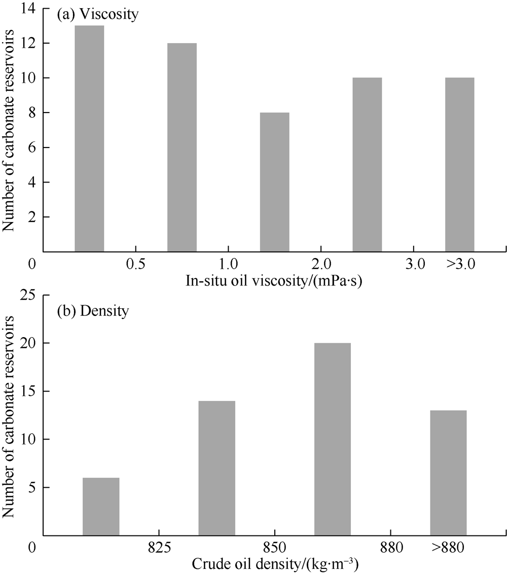 | Fig. 4. Statistics on oil viscosity and density of 53 carbonate reservoirs in the Middle East. |
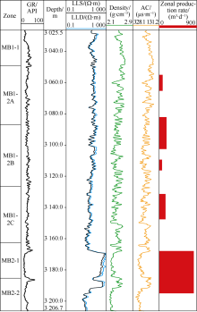
Affected by both sedimentation and diagenesis, carbonate reservoirs in the Middle East show strong lateral and vertical heterogeneity[13, 14, 15, 16]. Taking the Mishrif reservoir in Halfaya Oilfield as an example, the formation thickness is 120-350 m and it shows strong vertical heterogeneity due to multiple sedimentary cycles and superposition of different sedimentary facies (Fig. 5a). In addition, diagenesis is selective for different sedimentary facies. For instance, the top of grain shoal is more likely to be exposed to form secondary dissolved pores, which improves the permeability and further increases the vertical heterogeneity of the reservoir. Furthermore, the permeability of the top of the high-quality grain shoal in MB2-2 sublayer after exposure and dissolution, can be up to hundreds milli-darcy. The average permeability of the MB1-2C sublayer, which is composed of mainly lagoon deposits in restricted platform, is only (2-3) × 10-3μ m2 (Fig. 5b). The difference of primary sedimentary materials and texture between different sedimentary facies and migration with sea level fluctuation result in high lateral heterogeneity in the reservoir. For instance, the petrophysical properties in the crest of the MB1-2 sublayer are obviously better than those in the flank. Meanwhile, permeability of MB1-2 sublayer is generally low, and barriers and baffles are well-developed, which makes efficient development challenging. Similar features can also be found in the Sarvark reservoir of the Azadegan Oilfield in Iran and some carbonate reservoirs in Middle East.
 | Fig. 5. Typical well logs and NW-SE trending reservoir section of Halfaya Oilfield. |
The principles of water flooding development for carbonate reservoirs in the Middle East are as follows.
(1) Based on the characteristics of generally low oil viscosity and light oil in the Middle East, water flooding is adopted as the main development option. The formation water in carbonate reservoirs of the Middle East is generally with high salinity (normally 150-200 g /L), and the injected water usually comes from the formation water after a simple treatment, which still has high salinity and bacteria content. If the water cut is high, it not only increases the cost of produced water treatment, but also leads to corrosion problems for wellbores and surface pipelines. Thus, the overall goal of water flooding development is to ensure the maximum recovery under none and low water cut stage and to avoid corrosion.
(2) Because baffles are stably developed for carbonate reservoirs in the Middle East, the water flooding development should adopt zonal injection. Because most of the carbonate reservoirs in the Middle East are medium-thick and thick, with thickness greater than 50 m (Table 1) and with various vertical petrophysical properties and heterogeneity. Commingle injection and production would result in uneven water flooding front along with high-permeability channels, early water breakthrough, and fast water-cut development, etc. Zonal water injection can effectively improve the performance of water flooding. At the mean time, flexible and diverse well types can be used to increase the contact area between wells and reservoirs, so as to improving the injection and production capacity. The simple and applicative zonal water injection technology can be used to enhance the development degree on the reservoir.
(3) The carbonate reservoirs in the Middle East have none to low shale content, and they have good lateral connectivity. So it is suitable to adopt larger injection-production well spacing for water flooding development. As the pressure transmission speed is fast in the water flooding development of carbonate reservoirs in the Middle East, smaller well spacing is likely to cause early water breakthrough of producers.
(4) For the multimodal characteristics of pore structures in the carbonate reservoirs in the Middle East, moderate water injection rate development should be adopted by using the well pattern of “ low injection rate for single well with even and strong for the field” , so as to make full use of imbibition and effectively displace oil in small pores. If the water injection rate is too high, the injected water would flow preferentially along the macrospores or large channels, and the oil in the micropores or small channels would be difficult to displaced, resulting in lower recovery.
Since barriers and baffles exist in the medium-thick carbonate reservoirs, separated layer development is the prerequisite to ensure a successful water flooding development. Taking the Mishrif Formation in the Halfaya Oilfield as an example, the pay zone in this reservoir can be divided into six sublayers vertically, named as MB1-1, MB1-2A, MB1-2B, MB1-2C, MB2, and MC1. Each sublayer has a thickness of 10-30 m (Fig. 5a). The reservoirs have fairly high reserve abundance of (140-430) × 104 t/km2. There are low-permeability zones between these sublayers, including five sets of barriers and baffles and poor oil layers, among which MC1-2 marlstone baffle developed in the platform marginal slope is relatively stable. MB2-2 carbonaceous mudstone baffle deposited in the platform marginal marshes distributes locally. And three sets of marlstone and wackstone baffles in MB1-2 developed in lagoons of the platform have thin alternate interbeds, and MB1-1 has stable barriers and baffles across the whole structural area. These barriers and baffles are stably distributed across the whole oilfield. Fairly high reserve abundance of each sublayer lays a solid foundation for zonal water injection development in the Mishrif Formation. Based on reservoir characteristics and the distribution of barriers and baffles, the reservoir can be divided into three sets of development layer series, named as MB1-2A + MB1-2B, MB1-2C and MB2 + MC1 (Fig. 5b). Among them, MB2-MC1 is a bottom aquifer reservoir with good reservoir qualities, and the development scheme of bottom aquifer injection and mid-upper horizontal well production is applied. Permeability of MB1-2 is low and the reservoir has high thickness and a number of barriers and baffles. Thus, the reservoir can be divided into two sets of development units.
The carbonate reservoirs in the Middle East illustrated strong lateral and vertical heterogeneity. For lateral heterogeneity of such reservoirs, different types of water flooding well patterns should be applied in different areas. According to strong vertical heterogeneity, different well types are adopted to develop different types of reservoirs on the basis of development unit division. At present, there are various well types in the Mishrif Formation of the Halfaya Oilfield, including horizontal wells, multi-lateral wells, vertical wells and highly deviated wells. The MB1-2 reservoir of the Mishrif Formation in the Halfaya Oilfield is thick with well-developed barriers and baffles and low permeability (Fig. 5b), so it is divided into 2 sets of development units with water flooding. The oil bearing area of MB1-2A+MB1-2B is the largest, and five-point water flooding well pattern composed of mainly vertical and deviated wells is deployed at the crest area of the reservoir. In the flank area of the reservoir, the oil layers are thinner with poor reservoir qualities, and vertical wells would have low productivity. So highly-deviated wells or horizontal wells penetrating multiple layers are deployed for the flank area. Because there are multiple barriers and baffles developed in the thick MB1-2 reservoir, it is better to develop the reservoir by highly-deviated wells. The initial production rate of highly deviated wells is 1.2 times that of vertical wells and 1.1 times that of horizontal wells; at present, the production of highly deviated wells is 1.7 times that of vertical wells and 1.4 times that of horizontal wells. Similarly, Mishrif Formation in the Rumaila Oilfield has thick reservoir with good reservoir qualities in its northern part and thin reservoir with poor reservoir qualities in its southern part. The water flooding well pattern with a well spacing of 900 m was applied at the early stage. And at the later stage, different types of reservoirs are developed through well infilling in the north while the basic well pattern with a well spacing of 900 m is maintained in the south.
In addition, on the basis of development units division, the development degree of overall reservoir profile can be greatly improved by simple and applicative zonal water injection, thus enhancing the waterflooding sweep efficiency and recovery factor. After decades of development, CNPC featured technology of zonal water injection has developed to the fourth generation, which can achieve real-time monitoring and rate optimization for each intervals, and thus achieve the integrated waterflooding development of reservoir and engineering. Most carbonate reservoirs in the Middle East are under the early stage of water flooding development with commingled injection and production. The Mishrif Formation in the Halfaya Oilfield is under the primary depletion development at the early development stage. When all perforated intervals in vertical commingled wells are produced, the main production interval is the lower MB2 layer, which has good reservoir qualities. Its thickness accounts for only 15% of the total thickness, while its production rate accounts for more than 60% of the total production (Fig. 6a). At present, water injection pilot of the reservoir has started. The zonal water injection pilot will be conducted based on the results of development unit division, so as to improve the development degree on the profile and delay water breakthrough of producers with slow water cut development.
 | Fig. 6. Production logging test profile of a producer in Mishrif Formation of Halfaya Oilfield. |
Carbonate reservoirs in the Middle East are complex and diverse, and they are mostly medium-thick massive bottom aquifer reservoirs. Moreover, there are some other types of reservoirs, such as massive bottom aquifer reservoirs, gas- capped bottom aquifer reservoirs and thin-layer weak edge aquifer reservoirs. According to the study on several developed carbonate reservoirs in the Middle East, a set of high- efficiency water flooding development options for different types of carbonate reservoirs have been proposed based on their unique characteristics and the division of development units, including the combination of crestal gas injection and peripheral water injection, bottom-injection and top-production (buoyancy underpinning) and “ low injection rate for single well with even and strong for the field” areal well pattern development modes. Meanwhile, flexible and diverse well types are applied to improve productivity and injectivity, and the simple and applicative zonal water injection technology is adopted to increase development degree of reservoir.
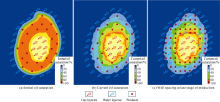
Some carbonate reservoirs in the Middle East are edge- bottom aquifer reservoirs with gas cap, and the energy of edge aquifer and gas cap is weak during the primary depletion of the reservoir. The aquifer energy difference and reservoir heterogeneity leads to uneven displacement front of edge aquifer, and the producers near gas cap are tend to experience gas channeling. Consequently, production rate declines significantly. For this type of reservoirs, the development mode of crestal gas injection in combination with peripheral water injection can be adopted, and the crestal gas injection can maintain the pressure of gas cap and the stability of oil-gas contact. Meanwhile, peripheral water injection can not only increase reservoir pressure, but also ensure uniform displacement of edge aquifer, thus realizing higher areal sweep efficiency and higher recovery factor. Fig. 7 illustrates an oil saturation distribution map for a carbonate reservoir with gas cap and edge aquifer in an oilfield in the Middle East. The development scheme of peripheral water injection and crestal gas injection is applied here. The displacement effect of peripheral water injection is good, and the waterflooding fronts are consistent and the remaining oil is concentrated near the oil-gas contact at the crest area. Furthermore, the oil-gas contact almost remains unchanged (Fig. 7b). At present, this reservoir has reached a recovery of 30%, with a water cut of only 11%, displaying good development performance. If the oil bearing area is large enough, the well pattern could be changed to the combination of peripheral injection, areal well pattern and crestal gas injection (Fig. 7c) at the later development stage. With more injectors added, reservoir pressure could be maintained and reservoir productivity could be improved.
 | Fig. 7. Comparison of well pattern and oil saturation distribution at different times of a carbonate reservoir in the Middle East (the yellow part is gas cap). |
For reservoirs with bottom aquifer or weak bottom aquifer, when the barriers and baffles are not developed, bottom-injection and top-production (buoyancy underpinning) is optimum development option. For example, this development scheme is currently applied in the Daleel Oilfield in Oman, al-Ahdeb Khasib2 reservoir, Halfaya MB2+MC1 reservoir and so on. For this kind of reservoirs, horizontal well can be placed at the top interval of the reservoir by natural depletion at the early development stage. After reservoir pressure decreased, water injection can be conducted near or below the oil-water contact with vertical or horizontal wells for pressure support.
MB2+MC1 development unit of Mishrif formation in Halfaya Oilfield is approximately a massive bottom aquifer reservoir with good reservoir qualities. In order to extend the none or low water cut production period, horizontal wells are used to produce at the top of the reservoir, and the completion interval of horizontal well should be kept away from the bottom aquifer as far as possible. It is recommended that the perforation section in horizontal well is far away more than 20 m from the oil-water contact. The bottom aquifer injection can be carried out by old vertical wells or new horizontal wells, and the water injection interval is near or below the oil-water contact. The bottom injection pilot has been carried out at present. The Shuaiba Reservoir in Daleel Oilfield of Oman is a thin carbonate reservoir and the Ahdeb Khasib2 reservoir is a medium-thickness, weak bottom aquifer reservoir, which both applied a linear well pattern of horizontal wells with bottom-injection and top-production currently. Among them, the average oil layer thickness in the Daleel Oilfield in Oman is 10-30 m, which is a thin carbonate reservoir of low permeability (Table 1). Its current oil recovery is over 28% and water cut is around 65%, indicating good waterflooding development performance.
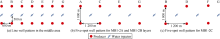
The development scheme of areal well pattern of “ low injection rate for single well with even and strong for the field ” is the most commonly used method in carbonate reservoirs development in the Middle East at present. It is applied in MB1 layer of the Mishrif Formation of Halfaya, the Mishrif Formation of Rumaila, the Mishrif Formation of West Gurna, and the Azadegan Oilfield of Iran, etc. On the basis of division of development units, robust “ low injection rate for single well with even and strong for the field” areal well patterns have been gradually established. During the initial primary depletion stage of the Rumaila Oilfield, a well spacing of 900 m was adopted with the vertical well pattern. As soon as the reservoir pressure approached the bubble point pressure, the line drive and the inverted nine-spot pattern water flooding pilots were carried out, and now the expanded inverted nine-spot pattern water flooding pilots has been started. The average water breakthrough time of producers is about one year according to the 900 m well spacing pattern. During the later stage, the well pattern will be gradually infilled and converted into a five-spot well pattern of “ low injection rate for single well with even and strong for the field” (Fig. 8a). The basic well pattern is aiming to develop Type I and II reservoirs, and the infilling well pattern is used to develop Type II and III reservoirs (Fig. 8b). Some oilfields in Middle East adopted the development scheme of peripheral water injection or the combination of peripheral water injection with crestal gas injection at the early stage. As soon as the oilfield development entered the middle and late stage, they would be gradually converted into the areal well pattern of “ low injection rate for single well with even and strong for the field” , leading to comprehensively improve the development degree and achieve larger sweep efficiency.
 | Fig. 8. Schematic diagram of the areal waterflooding well pattern with “ low injection rate for single well with even and strong for the field” . |
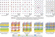
During the early development stage of the Mishrif major reservoir in the Halfaya Oilfield, horizontal producers with vertical injectors well pattern is deployed in row pattern with a well spacing of 500 m (Fig. 9a). Wells are commingled injection and production, currently the basic well pattern has been established. Through years of development and water injection pilot, several development challenges in this kind of thick carbonate reservoirs are emerged, including strong heterogeneity and performance difference between different layers, obvious conflicts between layers, low water flooding sweep efficiency, and early water breakthrough caused by the commingled injection and production. Well pattern should be optimized based on current well pattern with limited new wells. In order to ensure the full development of the whole reservoir, the main reservoir of the Halfaya Mishrif formation is divided into three sets of development units. For MB1-2 development units, considering that small well spacing would easily lead to early water breakthrough and rapid increasing of water cut, the original well pattern was made sparser. The 500 m normal line well pattern in the middle of MB1-2 reservoir is converted into an 800-1 000 m five-spot vertical well pattern for each development unit (Fig. 9). The producers in Line A, C, E and G in the original well pattern are converted into the corner wells in MB1-2A + MB1-2B five-spot well pattern, and the water injectors in Line B, D and F are converted into their corresponding injectors (Fig. 9b). While the producers in Line B, D and F are converted into the corner wells of MB1-2C five-point well pattern, and the water injectors in Line A, C, E and G are converted into their corresponding injectors (Fig. 9c). It obviously increases the well spacing of each development units and avoids early water breakthrough. During the middle and late stage of development, the converted sparse well patterns can then be merged into a dense well pattern with a 500 m well spacing to improve the development degree of low permeability reservoirs depending on the distribution of remaining oil.
 | Fig. 9. The well pattern coarsening in the middle of MB1-2 oil layer of Halfaya and the schematic diagram for layouts of edge injection and production well patterns. |
Since the pressure in carbonate reservoirs in the Middle East transmitted rapidly and far after water injection, a large well spacing well pattern is generally adopted for water injection and development. Regardless of low permeability reservoirs or medium-high permeability reservoirs, the well spacing is generally greater than 700 m, and in some cases it even exceeds 1 000 m. For example, the vertical well pattern with a 900 m well spacing is adopted in the Mishrif Formation of Rumaila and West Qurna for water injection development. And 500 m line spacing in MB1-2 layer in the Mishrif formation of Halfaya is currently applied, and it will be adjusted into an 800-1 000 m well pattern by well spacing coarsening later. Oilfield 3 in Middle East is a carbonate reservoir with medium permeability. During the early development stage of Oilfield 3, the peripheral water flooding was applied. The well spacing between the peripheral injectors and the producers was 2 000-5 000 m, and the pressure around producers are effectively supplied. The peripheral water injection is also applied in Middle East 2 Oilfield, and the average well spacing between the peripheral injectors and the producers is 2000 m. At present, this oilfield has a recovery percent of 19% with a water cut of only 15%.
Since the carbonate reservoirs in the Middle East are characterized by strong heterogeneity and commonly multimodal pore structure, sound development strategies of water flooding should also be optimized under the appropriate water flooding development scheme. Moderate water injection rate is recommended to maintain reasonable pressure drawdown and voidage replacement ratio.
For producers, controlling the single well pressure drawdown is the main method to achieve better performance of water injection. By comparing the single-well pressure drawdown in carbonate reservoirs with different reservoir qualities in the Middle East (Fig. 10), it is found that for the carbonate reservoirs with a permeability greater than or equal to 20 × 10-3 μ m2, the overall single-well pressure drawdown needs to be controlled below 4 MPa. For carbonate reservoirs with a permeability less than 20 × 10-3 μ m2, the pressure drawdown needs to be increased appropriately so as to ensure a certain production capacity, which can be controlled below 7 MPa.
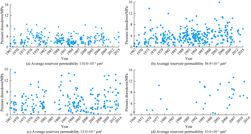 | Fig. 10. Comparison of pressure drawdown of wells in carbonate reservoirs with different reservoir qualities in the Middle East. |
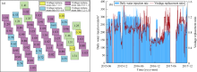
Voidage replacement ratio is the key factor to maintain reservoir pressure and control water cut increasing. If the voidage replacement ratio is greater than 1, the reservoir pressure will gradually increase. On the other hand, if it is less than 1, the reservoir pressure will gradually decrease. However, the carbonate reservoirs in the Middle East are commonly developed by natural depletion at the early stage, and then by water injection. Therefore, reservoir pressure gradually decreases during primary depletion and will be gradually recovered after water injection. Considering the strong heterogeneity of carbonate reservoirs in the Middle East, the voidage replacement ratio should be kept between 0.8-1.2 during the water flooding development. So relatively even areal displacement front can be achieved by water injection. The injection rate and voidage replacement ratio should be kept low in order to avoid rapid water breakthrough by water injection along the high-permeability channel. When the edge and bottom aquifer is strong, the voidage replacement ratio could be controlled below 1 in order to make full use of the edge and bottom aquifer. Fig. 11a shows the distribution of average voidage replacement ratio for a carbonate reservoir in the Middle East in 2017, which is a weak edge bottom aquifer reservoir and developed by areal well pattern. During water injection, the voidage replacement ratio should be kept near 1 (mainly 0.8-1.2) to maintain the reservoir pressure. The daily water injection rate of single well in Fig. 11b is maintained between 150-300 m3. And injection and production balance should be kept to achieve a good waterflooding performance.
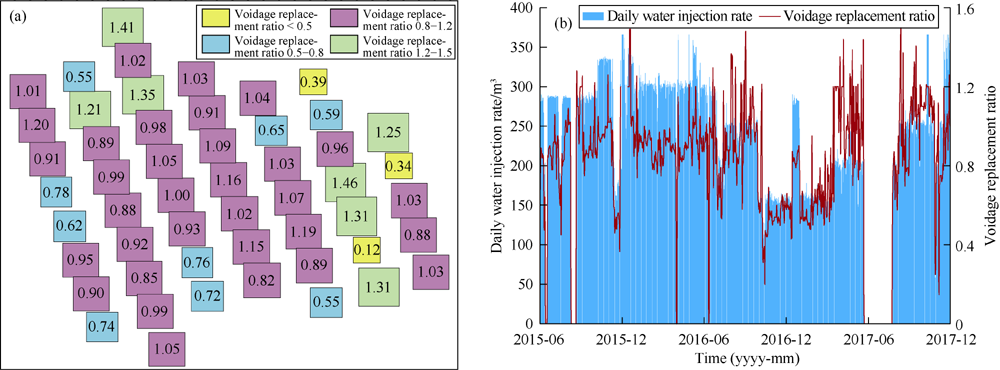 | Fig. 11. The distribution of average voidage replacement ratio of each injection group for a carbonate reservoir of Middle East in 2017 (a) and the water injection curves of typical well (b). |
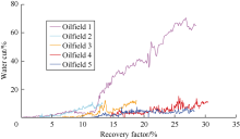
Fig. 12 shows the relationship between water cut and oil recovery of five typical waterflooding carbonate oil fields in the Middle East. Among them, Oilfield 1 adopts the bottom- injection and top-production development option, Oilfield 2 and Oilfield 3 adopt the water injection development strategy of the “ low injection rate for single well with even and strong for the field” areal well pattern. And Oilfield 4 and Oilfield 5 adopt the water flooding development mode combining crestal gas injection and peripheral water injection. Reasonable voidage replacement ratio and pressure drawdown are maintained during water injection, which achieve the uniform areal distribution of pressure and uniform displacement efficiency by injected water. Among them, 4 oilfields have reached a oil recovery factor of over 15% in the none and low water cut period, and the oil recovery factor of Oilfield 4 even exceeds 30% in the low water cut stage, which shows a good waterflooding performance.
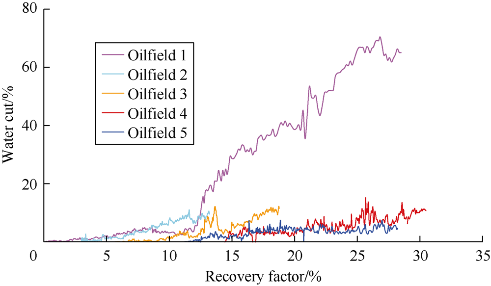 | Fig. 12. Water cut and recovery percent of five typical waterflooding carbonate oil fields in the Middle East. |
Carbonate reservoirs in the Middle East were all deposited in clean marine environment. It has some distinctive characteristics: low to none shale content, good lateral connectivity, fast and far pressure transmission, multimodal pore structure, fairly subtle poor reservoir quality baffles, low oil viscosity, high formation water salinity, and strong lateral and vertical heterogeneity.
Four principles should be followed in water injection development of carbonate reservoirs in the Middle East: water injection is the main method for pressure support; the division of development units with water injection should be adhered; large well spacing should be adopted for waterflooding; moderate water injection rate of well pattern is recommended, which is named as “ low injection rate for single well with even and strong for the field” .
Carbonate reservoirs in the Middle East are characterized by large thickness, obvious reservoir quality difference between different layers. On the basis of development units division, flexible and diverse well types should be adopted to develop different types of reservoirs, and injection profile control technologies such as simple and applicative zonal injection should be used to improve the control level and development degree of reservoir.
Different water flooding development schemes should be adopted for different types of carbonate reservoirs, including the combination of crestal gas injection with peripheral water injection, bottom-injection and top-production (buoyancy underpinning), and the areal well pattern of “ low injection rate for single well with even and strong for the field” . During water injection, the development strategies such as moderate water injection rate, strict control of pressure drawdown and voidage replacement ratio should be followed. The ultimate goal is to achieve the maximum recovery factor under none and low water cut stage.
The authors have declared that no competing interests exist.
| [1] |
|
| [2] |
|
| [3] |
|
| [4] |
|
| [5] |
|
| [6] |
|
| [7] |
|
| [8] |
|
| [9] |
|
| [10] |
|
| [11] |
|
| [12] |
|
| [13] |
|
| [14] |
|
| [15] |
|
| [16] |
|